

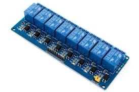
8 Channel Relay Module with Optocoupler KY-019 5V
KSh 1,000.00
Only 3 left in stock
The 8 Channel Relay Module with Optocoupler KY-019 5V is a board designed to interface low-voltage control signals (typically 5V from microcontrollers like Arduino, Raspberry Pi, etc.) with higher voltage or current circuits. It features eight independent relays, each isolated using optocouplers for enhanced safety and protection of the control circuitry. The “KY-019” likely refers to a specific design or series of relay modules.
Here’s a breakdown of its key features and characteristics:
Core Function:
- Amplification and Switching: Allows low-power signals to control high-power devices.
- Electrical Isolation: Utilizes optocouplers to provide galvanic isolation between the control side and the load side. This is a crucial safety feature, protecting the microcontroller from potentially damaging voltages or current surges from the switched circuits.
Key Components:
- Eight Relays: The module contains eight independent electromechanical relays. Each relay typically has three terminals for switching:
- Common (COM): The central contact.
- Normally Open (NO): The contact is open (disconnected from COM) when the relay coil is not energized. It closes (connects to COM) when the coil is energized.
- Normally Closed (NC): The contact is closed (connected to COM) when the relay coil is not energized. It opens (disconnects from COM) when the coil is energized.
- Eight Optocouplers: Each relay channel has its own optocoupler (also known as optoisolator). This component uses an LED and a phototransistor to transmit the control signal via light, ensuring no direct electrical connection between the input and output sides.
- Driving Transistors: Transistors are used to amplify the current from the optocoupler’s output to reliably drive the coils of the 5V relays.
- Flyback Diodes: Diodes are placed across each relay coil to suppress back EMF (voltage spikes) generated when the coil is de-energized. This protects the driving transistors and optocouplers.
- Status Indicator LEDs: Typically, there are LEDs for each channel to indicate when the corresponding relay is active (energized).
- Input Signal Pins: These are usually header pins for connecting the 5V control signals from a microcontroller (one pin per relay channel).
- Power Supply Connections: Pins for connecting the 5V power supply required to operate the relay coils and the module’s internal circuitry.
- Output Terminals: Usually screw terminals for easy and secure connection of the wires to the devices being switched.
Key Specifications (Typical):
- Number of Channels: 8
- Relay Coil Voltage: 5V DC (the module is designed to use 5V relays)
- Control Signal Voltage: Typically 5V (compatible with standard microcontroller logic levels)
- Maximum Switching Voltage (AC): Usually around 250V AC (check the relay’s markings)
- Maximum Switching Current (AC): Typically around 10A (check the relay’s markings)
- Maximum Switching Voltage (DC): Usually around 30V DC (check the relay’s markings)
- Maximum Switching Current (DC): Typically around 10A (check the relay’s markings)
- Trigger Type: Often “low-level trigger,” meaning the relay activates when the input signal goes low (0V). This is a common configuration for these types of modules.
- Dimensions: The physical size of the module will vary.
Advantages of Using the KY-019 5V 8 Channel Relay Module with Optocoupler:
- High Channel Density: Allows control of eight separate circuits.
- Electrical Isolation: Optocouplers provide excellent protection for the control circuitry.
- Easy to Interface: Designed for direct connection to 5V microcontroller outputs.
- Clear Status Indication: LEDs show the on/off state of each relay.
- Safety: Enhances safety when switching mains voltages or high-power loads.
- Protection: Flyback diodes protect the driving components.
Typical Applications:
- Home Automation: Controlling multiple lights, appliances, or other devices.
- Robotics: Activating various actuators, motors, and solenoids.
- Industrial Control: Interfacing with sensors, motors, and other equipment.
- Smart Agriculture: Controlling irrigation systems, lighting, and ventilation.
- DIY Electronics Projects: Any project requiring a microcontroller to switch multiple higher power loads safely.
Important Considerations:
- Load Ratings: Always check the voltage and current ratings printed on the relays themselves and ensure that the loads you are switching do not exceed these limits.
- Trigger Level: Confirm whether the module uses a high-level or low-level trigger to control the relays and program your microcontroller accordingly.
- Power Supply: Provide a stable 5V power supply with sufficient current to operate all eight relays simultaneously if needed.
The KY-019 5V 8 Channel Relay Module with Optocoupler is a popular and cost-effective solution for expanding the switching capabilities of microcontrollers while ensuring electrical safety through optocoupler isolation.
You must be logged in to post a review.
Related products
-
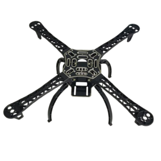
F450 Multi rotor Quad copter Air frame ( PREORDER ON OUR SALES CHAT LINE )
KSh 2,100.00Read moreThe F450 Multi-Rotor Quad Copter Airframe is a lightweight, durable frame designed for building your own quadcopter. …
F450 Multi rotor Quad copter Air frame ( PREORDER ON OUR SALES CHAT LINE )Read More
-
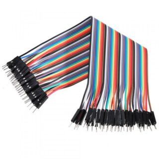
Male-to-Male Jumper Wires
KSh 140.00Add to cartMale-to-male jumper wires are essential components in electronics and prototyping projects. They are simple, flexible wires with connectors at both ends, both of which are typically male pins. These wires are widely used in connecting various electronic components on breadboards, circuit boards, or between different modules and sensors. Here are some key characteristics and uses of male-to-male jumper wires:
-
Male Header Pins Connectors
KSh 30.00Add to cartHeader pins, also known simply as headers or pin headers, are common electronic components used in various applications to create electrical connections between different components or devices. They consist of a row of metal pins encased in a plastic or insulating housing.


Products
-
 Pyrometer
KSh 18,500.00
Pyrometer
KSh 18,500.00
-
NodeMCU ESP-WROOM-32S WiFi Development Board
KSh 1,800.00
-
433MHz RF Transmitter and receiver
KSh 200.00
-
Max30205 contact temperature senor
KSh 1,800.00
-
DS18B20 Temperature Probe Sensor
Price range: KSh 300.00 through KSh 500.00

Reviews
There are no reviews yet.