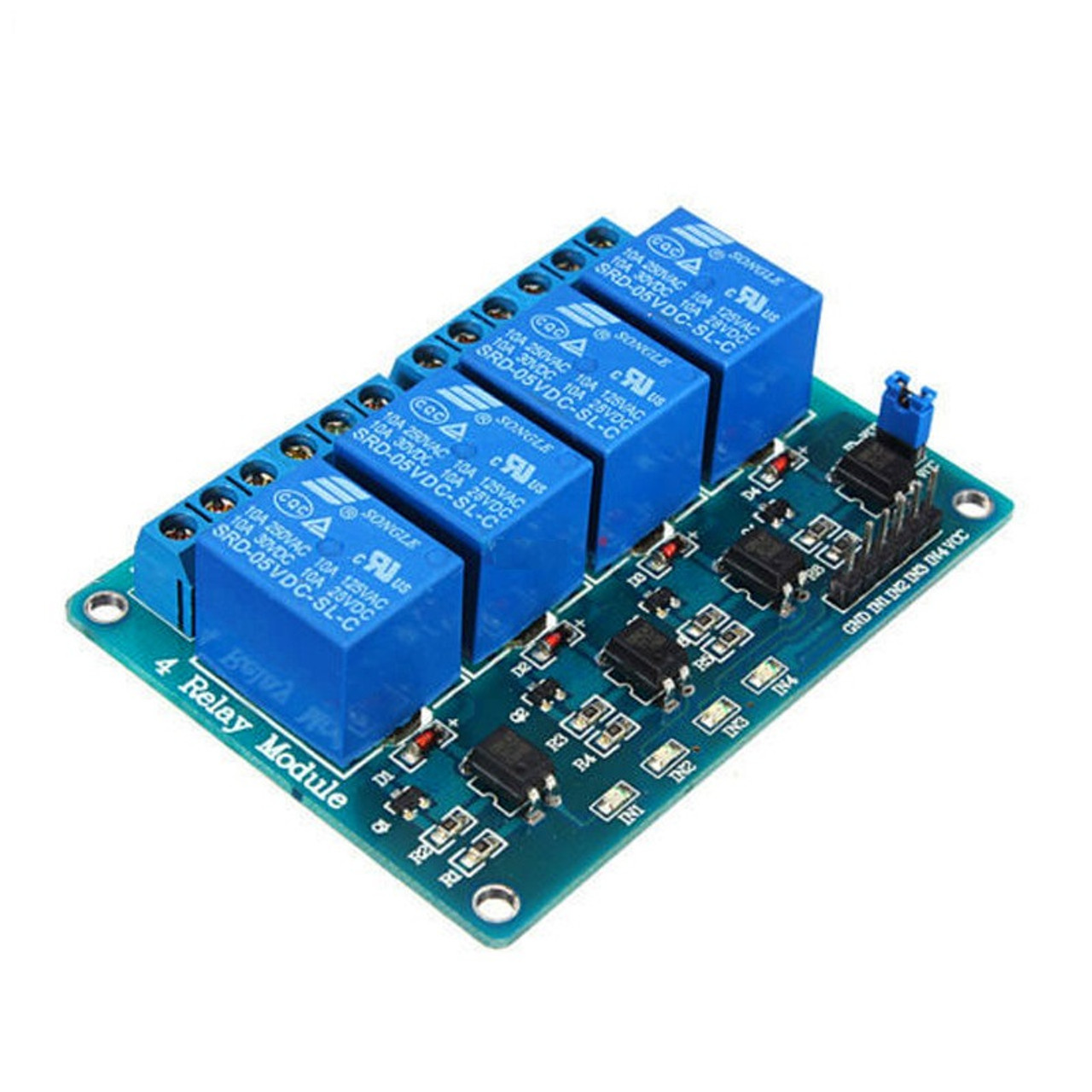
4 Channel Relay Module with Optocoupler
KSh 500.00
Only 2 left in stock
A 4 Channel Relay Module with Optocoupler is an electronic board designed to allow a low-power control signal (typically from a microcontroller like Arduino, Raspberry Pi, or PLC) to switch higher power circuits safely and with electrical isolation. It contains four independent relays, each capable of switching an AC or DC load, and crucially includes optocouplers for isolation.
Here’s a breakdown of its key features and characteristics:
Core Function:
- Amplification and Switching: It acts as an intermediary, allowing a low-current signal to control high-current or high-voltage devices.
- Electrical Isolation: The optocouplers provide crucial electrical isolation between the low-power control side (microcontroller) and the high-power load side (device being switched). This protects the microcontroller from potentially damaging voltage spikes or surges from the load circuit.
Key Components:
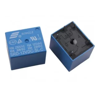
- Four Relays: The module features four independent electromechanical relays. Each relay typically has:
- Coil: Energized by the control signal to actuate the switch.
- Common (COM) Terminal: The input/output point of the switch.
- Normally Open (NO) Terminal: The circuit is open (disconnected) when the relay coil is not energized. It closes (connects to COM) when the coil is energized.
- Normally Closed (NC) Terminal: The circuit is closed (connected to COM) when the relay coil is not energized. It opens (disconnects from COM) when the coil is energized.
- Optocouplers (also known as optoisolators): These are integrated circuits that use light to transmit an electrical signal between two isolated circuits. They typically consist of an LED and a phototransistor.
- When a current flows through the LED on the input side (controlled by the microcontroller), it emits light.
- This light is detected by the phototransistor on the output side, causing it to conduct and energize the relay coil.
- Since the signal is transmitted via light, there is no direct electrical connection between the control and load circuits.
- Transistors (Drivers): These are often used to amplify the current from the optocoupler output to reliably drive the relay coil.
- Diodes (Flyback/Freewheeling Diodes): These are placed across the relay coils to protect the driving transistors and the optocouplers from voltage spikes that can occur when the inductive load of the relay coil is switched off.
- Indicator LEDs: Typically, there are LEDs to indicate the power status of the module and the activation status of each individual relay.
- Input Connectors: These are pins or screw terminals for connecting the control signals from the microcontroller.
- Output Connectors: These are usually screw terminals for connecting the wires to the devices being switched.
- Power Supply Connections: Terminals for providing power to the relay coils and the module’s internal circuitry. Often, there might be separate power inputs for the control side and the relay side, especially when using the optocoupler for isolation. Jumpers might be present to select whether to use a common power supply or separate ones.
Key Specifications (may vary between modules):
- Number of Channels: 4 (independent relays).
- Relay Coil Voltage: Typically 5V or 12V DC (check the module specifications). This is the voltage needed to activate the relays.
- Control Signal Voltage: Usually compatible with 3.3V or 5V logic levels from microcontrollers.
- Maximum Switching Voltage (AC): e.g., 250V AC.
- Maximum Switching Current (AC): e.g., 10A.
- Maximum Switching Voltage (DC): e.g., 30V DC.
- Maximum Switching Current (DC): e.g., 10A. Always check the specific ratings marked on the relays themselves.
- Optocoupler Type: Common types include EL817 or similar.
- Trigger Level: Can be either “low-level trigger” (relay activates when the control signal goes low) or “high-level trigger” (relay activates when the control signal goes high). This is often configurable via jumpers on the module.
Advantages of Using a Relay Module with Optocouplers:
- Electrical Isolation: Protects the microcontroller from high voltages and currents.
- Safety: Provides a safer way to control mains-powered devices.
- Noise Reduction: Optocouplers can help reduce electrical noise between the control and load circuits.
- Easy Interfacing: Simplifies connecting microcontrollers to high-power loads.
- Clear Indication: Status LEDs provide visual feedback on relay operation.
Typical Applications:
- Home Automation: Controlling lights, fans, motors, and other appliances.
- Robotics: Activating motors, solenoids, and other actuators.
- Industrial Control: Interfacing low-power control systems with high-power machinery.
- Smart Agriculture: Controlling pumps, valves, and lighting systems.
- DIY Electronics Projects: Any project where a microcontroller needs to switch higher power loads safely.
When using a 4 Channel Relay Module with Optocouplers, it’s crucial to understand the voltage and current ratings of the relays and the trigger level of the module to ensure safe and proper operation. Always refer to the datasheet of the specific module you are using.
You must be logged in to post a review.
Related products
Products
-
 Screw set
KSh 50.00
Screw set
KSh 50.00
-
 5V power adapter
KSh 1,000.00
5V power adapter
KSh 1,000.00
-
Passive buzzer
KSh 50.00
-
Oraimo Micro USB cable for ESP
KSh 300.00
-
SCT-013-000 50mA 30A Switching Current Transformer sensor
KSh 1,500.00
Reviews
There are no reviews yet.