
Your Arduino can blink an LED, but it can’t power a bulb, a fan or a water pump on its own. Its pins give out a tiny current at 5 V (or 3.3 V on an ESP32). A relay module is the bridge: a small signal from your board flips a switch that controls a separate, bigger circuit. In this guide you’ll learn how to connect a relay module to Arduino or ESP32, what every pin does, sample code, and the safety rules that matter.
Quick answer: connect the relay module’s VCC to 5V, GND to GND and IN to a digital pin. Then wire your load through COM and NO. Set the pin LOW or HIGH in code to switch it (many modules switch ON when IN is LOW).
What is a relay?
A relay is a switch you control with electricity. Inside is a small coil. When current flows through the coil, it becomes a magnet and pulls a metal contact across, closing a second circuit. The two circuits never touch, so your microcontroller stays separated from the load it’s switching.
A relay module puts that relay on a small board with everything it needs: a transistor to drive the coil, a protection diode, an indicator LED and, on many boards, an optocoupler for extra isolation. That’s why beginners use modules instead of bare relays.
Prefer to watch? Here’s our 42-second Tech Explained video:
The pins on a relay module
A relay module has two sides.
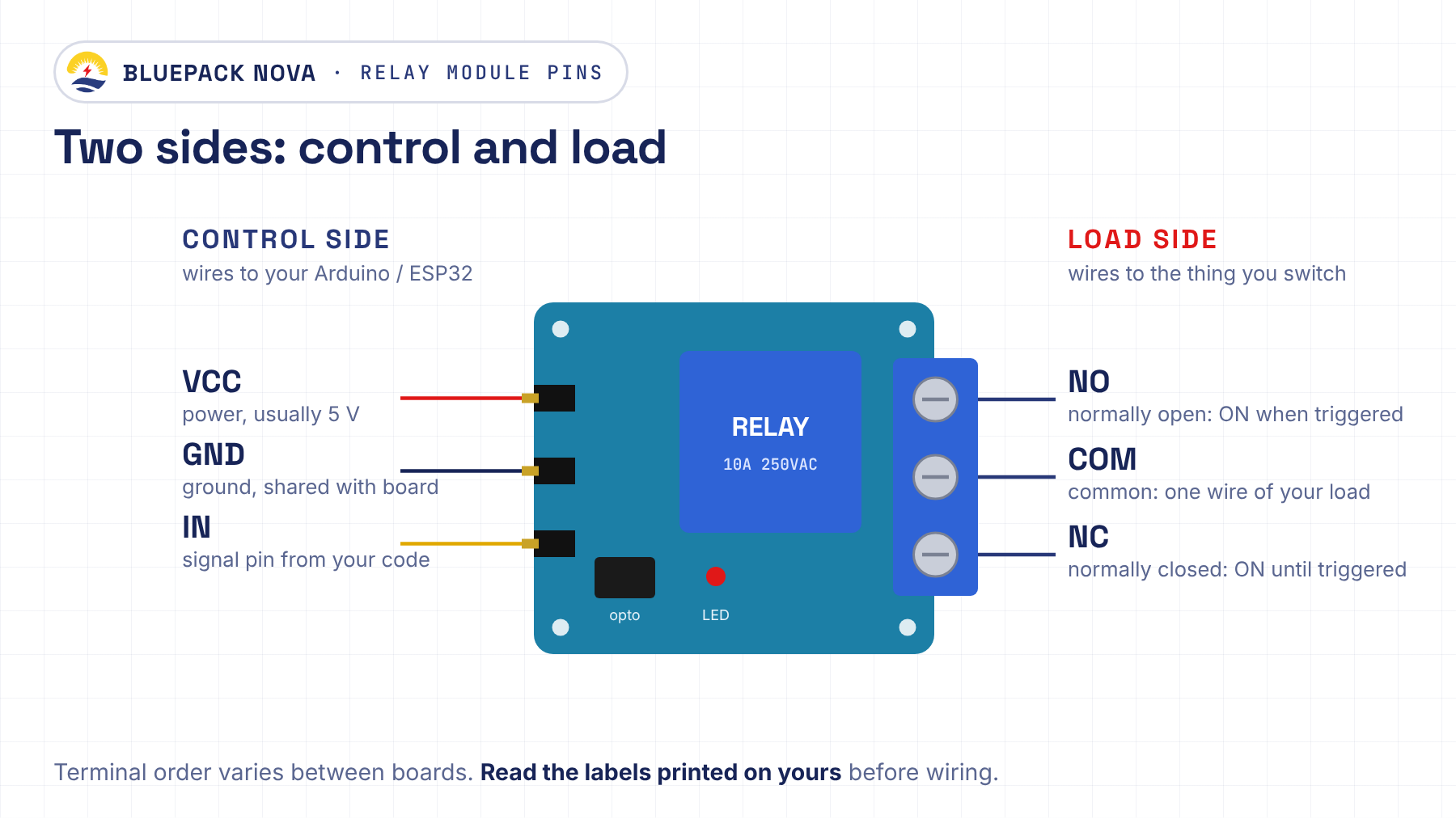
Control side (connects to your Arduino or ESP32):
- VCC: power for the module, usually 5 V.
- GND: ground, shared with your board.
- IN (or IN1, IN2… on multi-channel boards): the signal pin. Your code sets it HIGH or LOW to switch the relay.
Load side (the screw terminals, connected to what you’re switching):
- COM (common): the moving contact. One wire of your load circuit goes here.
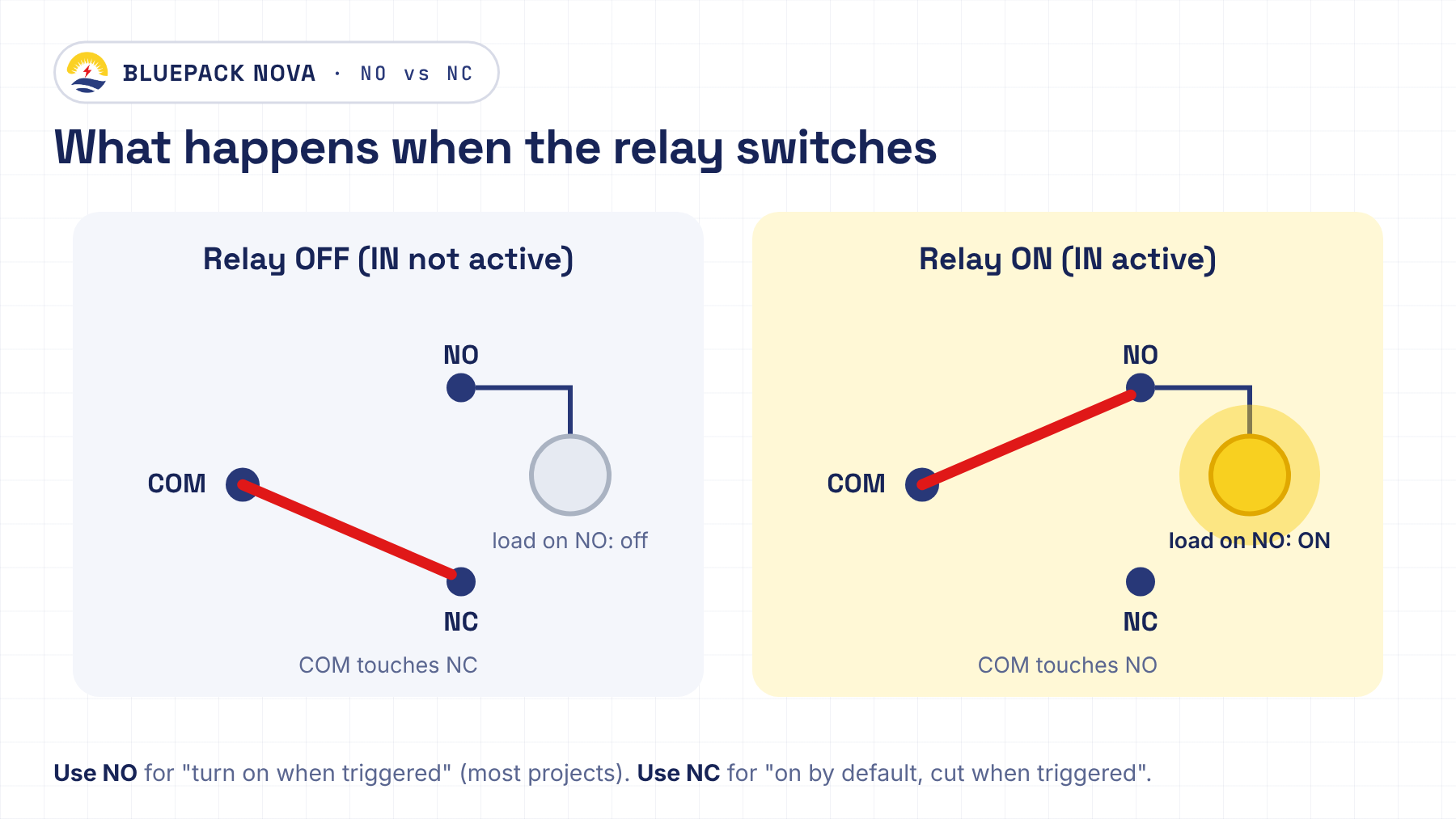
- NO (normally open): disconnected from COM until the relay switches on. Use this for “turn on when triggered”, for example a light that comes on when motion is detected.
- NC (normally closed): connected to COM until the relay switches on. Use this for “on by default, cut when triggered”.
What you need
- An Arduino Uno or an ESP32 DevKit (30-pin)
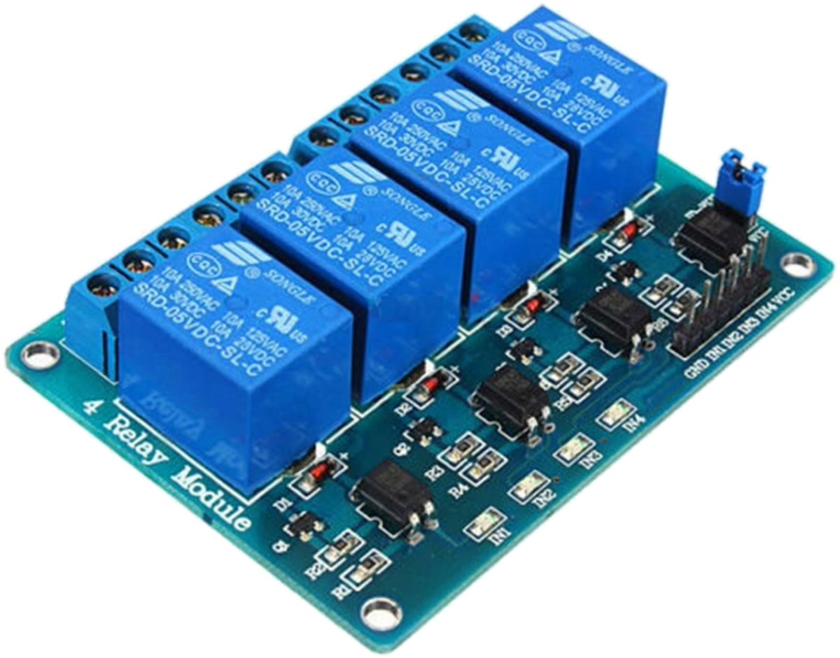
- A relay module: 2-channel 5V relay, 4-channel relay with optocoupler or 8-channel relay
- Jumper wires (female-to-male are handiest for module pins)
- A low-voltage load to practise with, such as a 12 V LED strip or a small 12 V fan, plus its own power supply
How to connect a relay module to Arduino
- Module VCC → Arduino 5V
- Module GND → Arduino GND
- Module IN1 → Arduino digital pin 7
- Load side: put the relay in one wire of your 12 V circuit. Supply + → COM, NO → load +, load − → supply −.
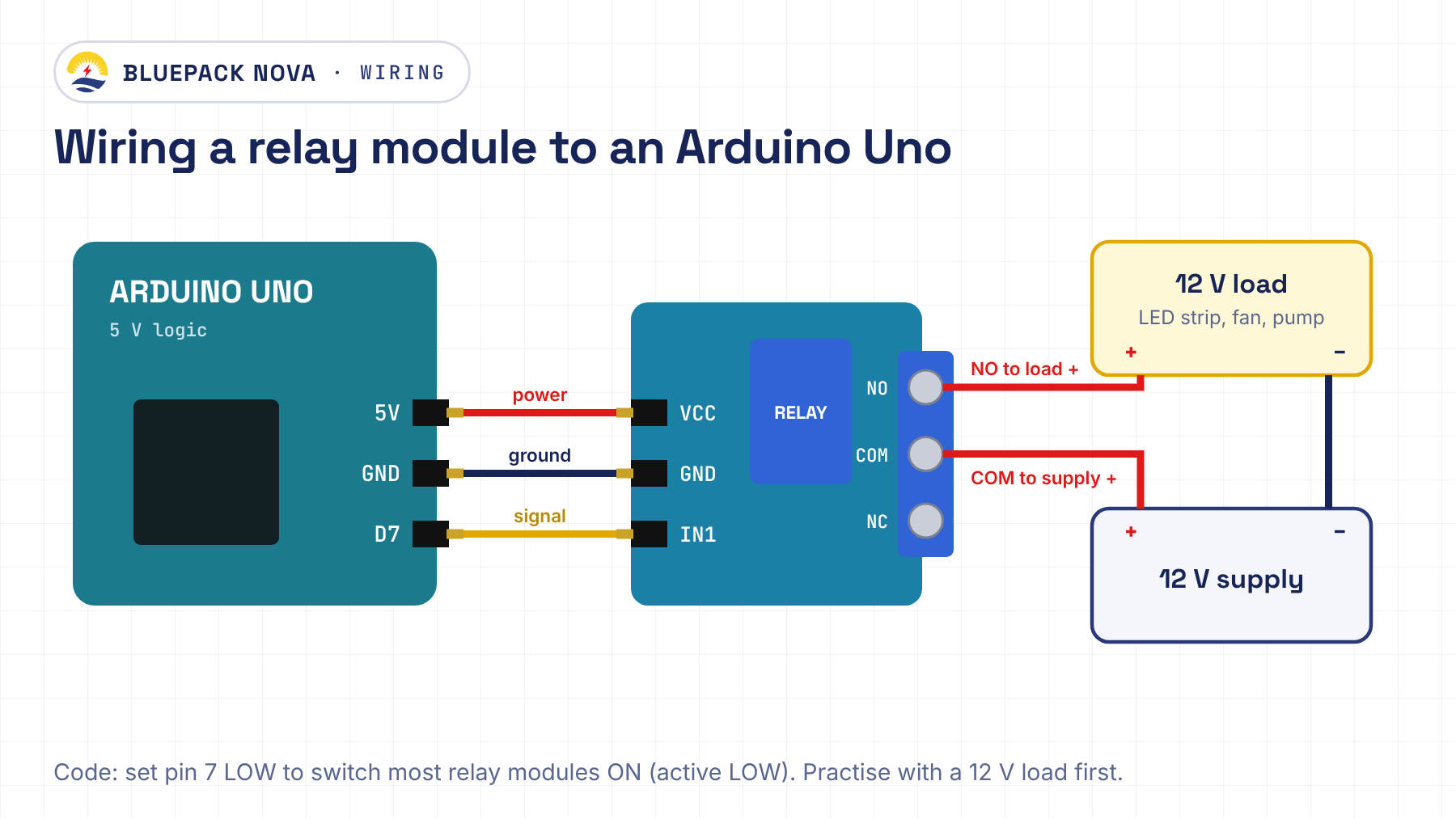
Upload this sketch. The relay should click on for 2 seconds, then off for 2 seconds:
// Bluepack Nova: relay module test
const int RELAY_PIN = 7;

// Many relay modules are "active LOW": IN = LOW switches the relay ON.
// If yours works the other way round, swap these two values.
const int RELAY_ON  = LOW;
const int RELAY_OFF = HIGH;

void setup() {
  digitalWrite(RELAY_PIN, RELAY_OFF); // start with the relay off
  pinMode(RELAY_PIN, OUTPUT);
}

void loop() {
  digitalWrite(RELAY_PIN, RELAY_ON);
  delay(2000);
  digitalWrite(RELAY_PIN, RELAY_OFF);
  delay(2000);
}
Tip: active LOW vs active HIGH. Many relay modules switch on when the IN pin is pulled LOW. If your relay is on when you expected it off, swap RELAY_ON and RELAY_OFF. Setting the pin to “off” before pinMode() stops the relay from clicking on for a moment at power-up.
How to connect a relay module to ESP32
The wiring is the same idea, with one difference: ESP32 pins work at 3.3 V, while most relay modules are built for 5 V.
- Module VCC → ESP32 VIN (5 V from USB) or a separate 5 V supply
- Module GND → ESP32 GND (and the supply’s ground, if you use one)
- Module IN1 → ESP32 GPIO 26 (avoid GPIO 6–11 and the boot pins 0, 2, 12 and 15)
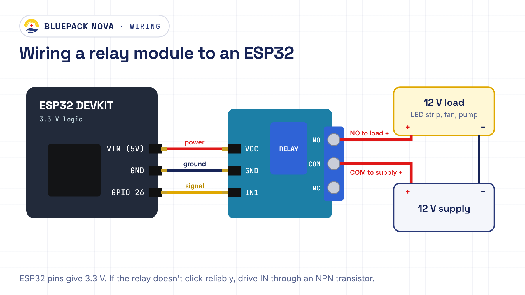
Use the same sketch with const int RELAY_PIN = 26;. Many optocoupler relay modules switch reliably from a 3.3 V signal, but not all do. If the LED lights but the relay doesn’t click, or it switches unreliably, drive the IN pin through a small NPN transistor, or use a relay module rated for 3.3 V logic.
The ESP32’s real strength is Wi-Fi: with the same wiring you can switch the relay from your phone, a web page or a schedule. That’s the core of most home automation projects.
Powering more than one relay
Each relay coil draws roughly 70–80 mA when it’s on. One relay is fine on your board’s 5 V pin. Four or eight relays switched on together can overload a USB port or the board’s regulator, causing resets and random behaviour. For multi-channel modules, power VCC from a separate 5 V supply and connect all grounds together.
Can a relay switch mains (240 V) power?
Yes, relays can switch mains, as long as the relay is rated for the voltage and current (check the rating printed on it, such as 10A 250VAC) and it’s wired correctly. Common relay modules are often rated around 10 A at 250 VAC, but treat the printed rating as the maximum, not a target, and stay well below it for motors and heaters.
Mains electricity can kill. If you switch mains:
- Practise with 12 V loads first until your circuit and code are reliable.
- Switch the live wire, never the neutral, and add a correctly rated fuse.
- Put the module in a closed, non-conductive enclosure so no one can touch the screw terminals or the solder joints underneath.
- Never work on the circuit while it’s plugged in.
- If you’re not sure, have a qualified electrician check your wiring before you plug in.
Common problems and fixes
- The relay clicks but the load doesn’t turn on: check your load wiring uses COM and NO, and that the load’s own supply is on.
- The relay is on all the time: your module is probably active LOW. Swap the on/off values in the code.
- The board resets when the relay switches: the relays are drawing too much current. Use a separate 5 V supply for the module.
- Works on Arduino but not ESP32: it’s the 3.3 V signal. See the ESP32 section above.
Project ideas to try next
- Motion-activated light: a PIR sensor tells the Arduino someone walked in, and the relay switches on the light.
- Automatic water pump: a water level sensor switches the pump off before your tank overflows.
- Smart Shamba irrigation: a soil moisture sensor turns on a 12 V pump or a 12 V solenoid valve when the soil is dry.
- Wi-Fi switch: control a socket from your phone with an ESP32 web server.
Frequently asked questions
Why does my relay turn on when the pin is LOW?
Many relay modules are “active LOW”: the IN pin switches the relay on when it’s pulled to ground. That’s normal. Just swap the HIGH and LOW values in your code.
Can I power a relay module from the Arduino’s 5V pin?
Yes, for one or two relays. For four or more switching at the same time, use a separate 5 V supply and connect its ground to the Arduino’s ground.
Does a relay module work with ESP32 and ESP8266?
Usually, yes. Power the module from 5 V and connect IN to a GPIO pin. Because these boards give a 3.3 V signal, some modules switch unreliably; a small NPN transistor or a 3.3 V-trigger relay module fixes that.
What is the difference between NO and NC?
NO (normally open) is disconnected until the relay switches on. NC (normally closed) is connected until the relay switches on. Most projects use COM and NO.
How much can a relay switch?
Check the rating printed on the relay. The common SRD-05VDC-SL-C relay on these modules is marked 10A 250VAC, but stay well below that, especially for motors and heaters.
Get your parts
Every part in this guide is available at bluepacknova.com. Not sure which relay module fits your project? Send us your project idea on WhatsApp and we’ll tell you exactly what you need.

Top rated products
-
 TIP31C transistor
KSh 80.00
-
4WD ROBOT CHASSIS
KSh 2,300.00
-
AS608/R307 Optical Fingerprint Sensor
KSh 1,850.00
-
SIM800L V1 GSM Module
KSh 900.00




Leave a Reply
You must be logged in to post a comment.