

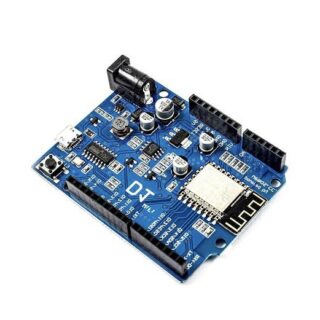
ESP8266 ESP-01 ESP01s adapter board for breadboard
KSh 140.00
In stock
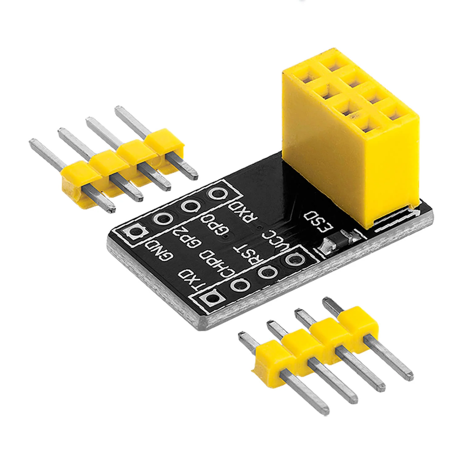
The ESP8266 ESP-01/ESP-01S Adapter Board for Breadboard is a small printed circuit board designed to make it easier to use the ESP-01 or ESP-01S Wi-Fi modules with a standard breadboard for prototyping.
Here’s a breakdown of its key features and description:
Purpose:
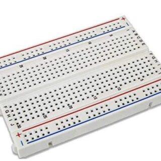
- Breadboard Compatibility: The primary purpose is to adapt the ESP-01/ESP-01S module’s pinout to be compatible with the 0.1-inch grid of a standard breadboard. The ESP-01 module has an unconventional dual-row, 2.54mm pin spacing that doesn’t directly fit breadboards.
- Simplified Prototyping: It eliminates the need for messy jumper wires directly connected to the tiny pins of the ESP-01, making wiring and experimentation much cleaner and more convenient.
- Clear Pinout Labeling: The adapter board typically has clear silkscreen labels indicating the function of each pin (VCC, GND, RX, TX, CH_PD, GPIO0, GPIO2, etc.), which helps prevent wiring errors.
Key Features:
- Compatibility: Designed to securely hold either the ESP-01 or the newer ESP-01S Wi-Fi module.
- Breadboard Friendly Pinout: It breaks out the ESP-01’s 8 pins to a single row of standard 0.1-inch spaced pins that can be easily plugged into a breadboard.
- Decoupling Capacitor: Many adapter boards include a 0.1µF decoupling capacitor on the power supply line (typically connected to the VCC pin). This capacitor helps to stabilize the power supply to the ESP8266 module, reducing noise and ensuring more reliable operation.
- Compact Design: The adapter itself is usually very small and doesn’t take up much space on the breadboard.
- Easy to Use: Simply plug the ESP-01/ESP-01S module into the female header on the adapter board, and then plug the adapter board into your breadboard. You can then easily connect other components and power to the clearly labeled pins.
Typical Pinout (aligned with breadboard rows):
When the ESP-01/ESP-01S is mounted on the adapter, the pins are typically arranged in a single row with the following connections (though the exact order might slightly vary depending on the specific adapter design):
- GND: Ground (0V)
- GPIO0: General Purpose Input/Output pin 0 (often used for flashing/boot mode control)
- GPIO2: General Purpose Input/Output pin 2
- VCC: Power supply (3.3V – Important: ESP8266 requires 3.3V, do not connect directly to 5V)
- RST/RESET: Reset pin (usually active low)
- CH_PD/EN: Chip Enable pin (active high, must be high for the ESP8266 to operate)
- TXD/TX: Transmit pin (UART)
- RXD/RX: Receive pin (UART)
In summary, the ESP8266 ESP-01/ESP-01S Adapter Board for Breadboard is an essential tool for anyone wanting to experiment with these popular Wi-Fi modules. It provides a convenient, reliable, and clearly labeled interface to connect the ESP-01/ESP-01S to a breadboard for easy prototyping and development of IoT and Wi-Fi-enabled projects.
You must be logged in to post a review.
Related products
-
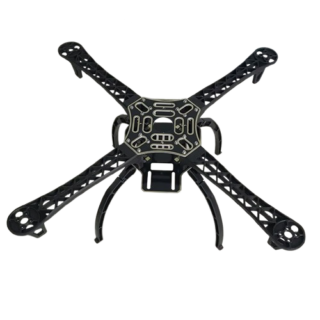
F450 Multi rotor Quad copter Air frame ( PREORDER ON OUR SALES CHAT LINE )
KSh 2,100.00Read moreThe F450 Multi-Rotor Quad Copter Airframe is a lightweight, durable frame designed for building your own quadcopter. …
F450 Multi rotor Quad copter Air frame ( PREORDER ON OUR SALES CHAT LINE )Read More


Products
-
 Pyrometer
KSh 18,500.00
Pyrometer
KSh 18,500.00
-
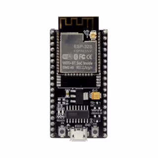
NodeMCU ESP-WROOM-32S WiFi Development Board
KSh 1,800.00
-
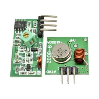
433MHz RF Transmitter and receiver
KSh 200.00
-
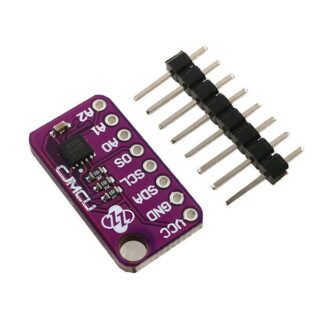
Max30205 contact temperature senor
KSh 1,800.00
-
DS18B20 Temperature Probe Sensor
Price range: KSh 300.00 through KSh 500.00

Reviews
There are no reviews yet.